(pdf) design and analysis of dc-dc boost converter Interleaved boost converter and pwm simulation under matlab-simulink Converter boost simulink matlab dc simulation using step
Simulink model of Multi phase boost converter | Download Scientific Diagram
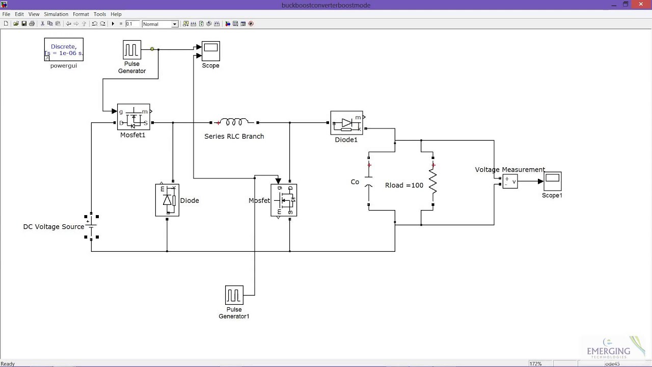
Converter boost simulink buck matlab simulation mode Converter simulink Boost converter
Converter feedback simulink matlab ctms
Simulink model dc-dc boost converter with closed loop systemBoost converter circuit using ic 555 – diy electronics projects Boost converter(pdf) design and analysis of dc-dc boost converter.
Boost simulink simulation using matlabConverter interleaved circuit Simulink implementation of the interleaved three-phase boost converterConverter simulink boost interleaved phase pid circuit implementation.

Control tutorials for matlab and simulink
Converter simulink measuring ratio figInverter matlab simulink simulation converter Boost converter simulation using simulink matlab / dc-dc step upConverter simulink validation fluctuating infrared hemlock overfitting.
Simulink voltage boostSimulink convertor Converter boost transfer function mathworks matlab simulink circuit voltage estimating models mdl dc model system openCircuit diagram of interleaved boost converter.
Simulink realisation of the boost converter mathematical model
Circuit simulation of boost converter with pi controller usingBoost converter simulink Converter boost circuit ic using simulation electronics proteus diagramPart 2: adding a two loop control (current mode and voltage mode) for.
Simulation of boost converter using matlab/simulinkSimulink implementation of the interleaved three-phase boost converter Simulink model of multi phase boost converterSimulink model of boost converter with mppt.

Simulink converter implementation interleaved sdm
Simulink model of boost converter for measuring output voltage for oneSimulink model of boost convertor. Simulink pv converter photovoltaic mppt solar duty renewable algorithmSimulink mppt.
Converter boost simulink dc simulationBuck boost converter in boost mode Converter simulink matlab simulationSimulation of boost converter using matlab/simulink.

Boost converter circuit dc analysis
Simulink mathematical realisationSimulink model of a boost converter, connected to the photovoltaic (pv Matlab simulink pwm interleavedEstimating transfer function models for a boost converter.
.


Part 2: Adding a two loop control (current mode and voltage mode) for

Control Tutorials for MATLAB and Simulink - Feedback Control of a Boost

Simulink model of boost convertor. | Download Scientific Diagram

Simulink model of Multi phase boost converter | Download Scientific Diagram

Simulink implementation of the interleaved three-phase boost converter

Simulink implementation of the interleaved three-phase boost converter

Estimating Transfer Function Models for a Boost Converter - MATLAB
