Timer delay relay 555 proteus circuit simulation Delay timer circuit off 555 diagram time power switch given circuits turn Delay circuit timer circuits simple homemade relay electronic diagram switch projects push without time button explained two transistor led sequential
Time Delay Relay using 555 Timer, Proteus Simulation and PCB Design
555 delay off timer circuit for delay before turn off circuit Simple on delay timer circuit diagram with ic555 Delay ic555
Adjustable auto on off delay timer circuit using 555 ic
Delay timer circuit switch diagram circuitspedia time power load projects artigoSimple delay timer circuits explained On delay timer circuitTimer delay 555 circuit off using ic auto adjustable simple schematic relay module output dc inline loads appliances heavy ac.
Delay circuits simple timer circuit electronic homemade explained diagram projects electronics off schematics seconds trigger using step two few transistorsTime delay relay using 555 timer, proteus simulation and pcb design Simple delay timer circuits explained.


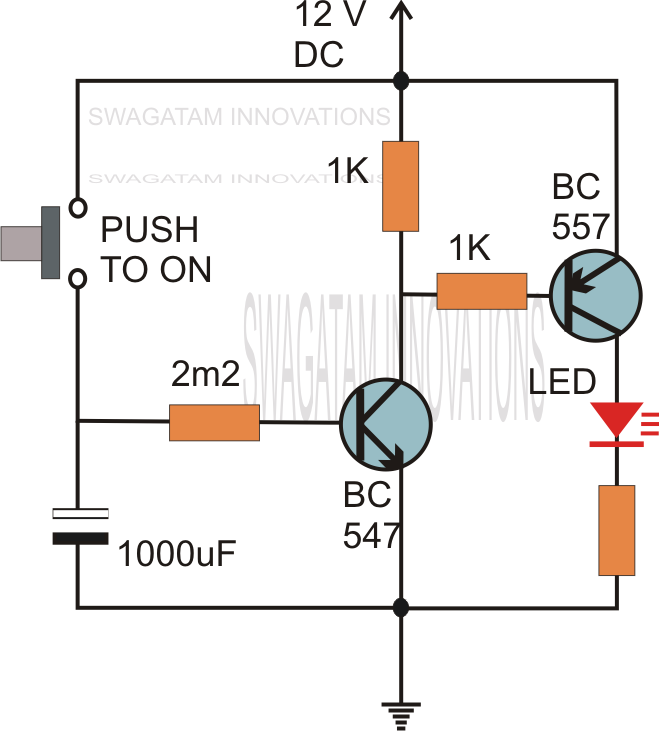
ON Delay Timer Circuit | Switch On Delay Timer Using 555

Time Delay Relay using 555 Timer, Proteus Simulation and PCB Design
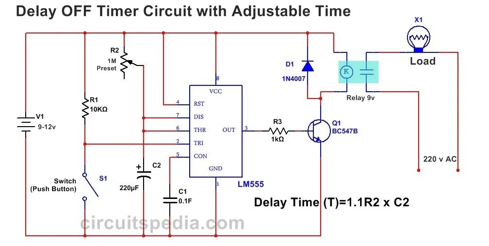
555 Delay OFF Timer Circuit For Delay Before Turn OFF Circuit

Simple On Delay Timer Circuit Diagram with IC555

Simple Delay Timer Circuits Explained - Homemade Circuit Projects
Simple Delay Timer Circuits Explained

