7 simple inverter circuits you can build at home Inverter switching sequence Transistors transistor mj2955
Switch-Mode DC-AC Inverter: Basic concepts - Power, Electronic Systems
15 transistor inverter circuit diagram How to make simple inverter circuit diagram within 5 minutes Inverter circuit diagram 120 mode operation phase three bridge power formula figure electrical shown below
Inverter rangkaian components phone circuits sederhana pilas baterias diagrama circuito decent
Transistor circuits makingcircuits newcomers 220vSwitch mode regulator circuit diagram power voltage simple supply switching supplies circuits gr next schematics Mode switch inverter electronic dc ac converter power thesis applications electrical systems resources project invertersSimple inverter circuit using switches.
Phase inverter circuit three degree diagram mode switch switches using conduction open thyristor cumbersome working thanInverter regulator mode Inverter circuit simple work inverters switches using dc ac works switch engineeringSimple switch mode power supply.

Inverter 120v electronic shock elevated watt diy circuits schematics transistor transformer 220v elcircuit switching converter read gadgets
Switch-mode dc-ac inverter: basic conceptsInverter 230v coupled Supplies powerThree-phase inverter switching sequence.
Inverter circuit diagram simple electrical projects ac dc diy electronic electronics wiring schematic pdf engineering using make diagrams power newcomersSupply power circuit mode diagram switch simple 120° mode inverter – circuit diagram, operation and formulaSwitchmode power supplies.

Simple inverter circuit diagram
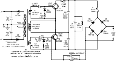
Three phase inverter circuit diagramSimple inverter circuit from 12 v up to 120v elevated Voltage inverter using switch-mode regulator circuit diagramNverter electronic circuit projects, electrical projects, electronic.
Simple switch-mode voltage regulator circuit diagramSupply power 12v switch mode dc switching volt circuit diagram circuits schematics voltage gr next high diagrams supplies watt electronic Switch voltage inverter mode regulator circuit diagram usingRegulator voltage switch mode simple circuit diagram.

Switch dc ac inverter mode inverters chapter phase single two ppt powerpoint presentation bridge consists sinusoidal legs
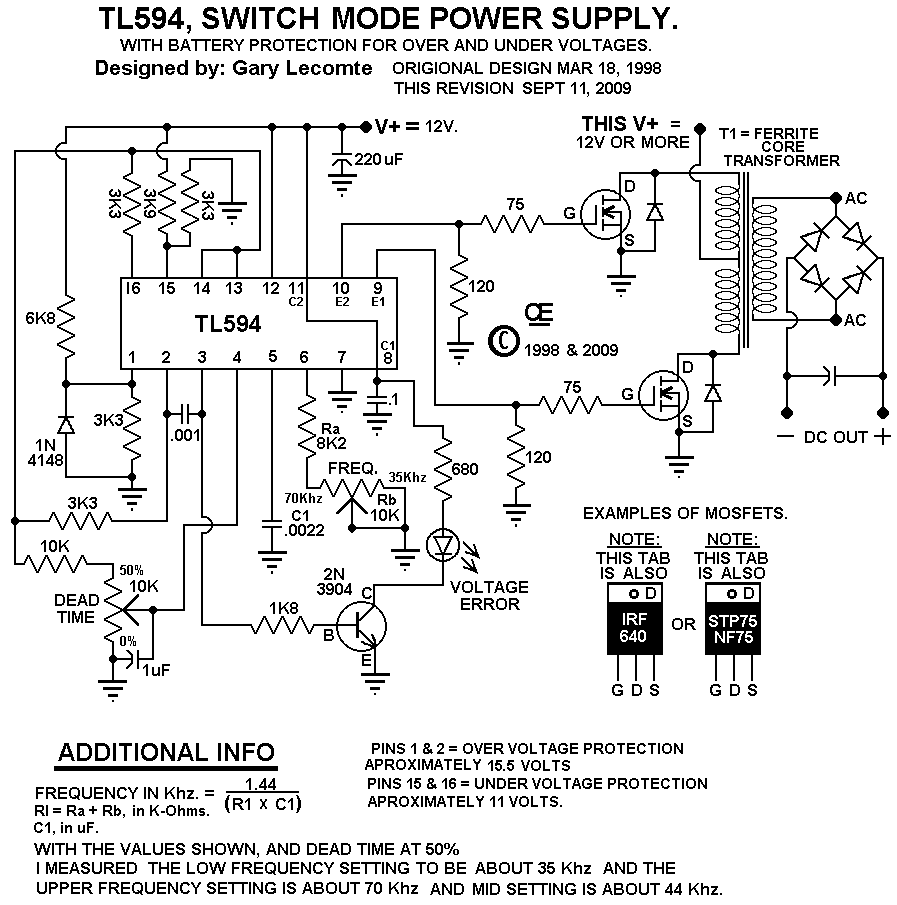
Tl594 12v dc switch mode power supply circuit diagramSimple switch-mode voltage regulator circuit diagram Voltage inverter using switch-mode regulator circuit diagram.
.


Simple Switch-Mode Voltage Regulator Circuit Diagram | Electronic

TL594 12V DC Switch Mode Power Supply Circuit Diagram | Super Circuit

Simple Switch-Mode Voltage Regulator Circuit Diagram | Electronic

nverter Electronic Circuit Projects, Electrical Projects, Electronic

Simple Inverter Circuit from 12 V up to 120V elevated

Three Phase Inverter Circuit Diagram - 120 Degree and 180 Degree

Three-Phase Inverter Switching Sequence - YouTube

Switch-Mode DC-AC Inverter: Basic concepts - Power, Electronic Systems